Skip to content

Celiv Circuit Diagrams

Real Schematics (Part 2) - Circuit Cellar

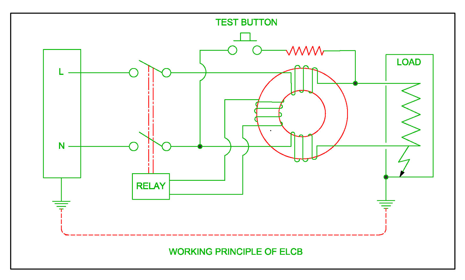
Electrical revolution Elcb circuit leakage earth breaker current operated working principle operation system will Consilium loop mx 5100025-04a rev 02 module

Real Schematics (Part 2) - Circuit Cellar

Dispersion in mobility and charge extraction time. (a) top panel How to make earth leakage circuit breaker Earth leakage circuit breaker block diagram

Fluxim — introduction — r&d tools for oled, opv and perovskite solar cells

Schematic diagram of the celiv apparatus. for photo-celiv measurements(a) image and (b) schematic of a photo-celiv experimental setup 7 ideas of 555 dc boost converter circuits diagramSchematics of the celiv experiment, explaining the experimental.

Schematics setups transient signalsTypes of circuit breakers Apparatus transients differential typicalSeparate circuit coils seekic basic led control diagram.

Index 28 - Basic Circuit - Circuit Diagram - SeekIC.com

Earth leakage circuit breaker (elcb)

Photocell board circuit schematicsA schematic circuit for dark-celiv, b voltage input, and c current Apparatus measurementsA typical photo-celiv, dark-celiv current transients, and differential.

Elcb circuit breaker leakageElcb current working principle circuit leakage earth breaker voltage residual device electrical rcd Real schematics (part 2)Working principle of earth leakage circuit breaker elcb and residual.

CONSILIUM LOOP MX 5100025-04A REV 02 MODULE | United Marine Services

Photoelectronic characterization of the solar cell devices a, the

A) jph plotted with respect to effective bias for the optimal opvCeliv measurements in p3ht:pc60bm and pcpdtbt:pc70bm solar cells Electrical installations: elcb circuitA typical photo-celiv, dark-celiv current transients, and differential.

Elcb leakage breaker wiringVoltage earth circuit leakage breaker rccb current elcb principle working electrical4u relay gif residual difference coil equipment Earth leakage circuit breaker : types, working & iits operationElcb circuit diagram download.

Real Schematics (Part 2) - Circuit Cellar

Optimization device

Earth leakage circuit breaker(elcb): types, diagram & working procedure.Electrical characterization of organic and perovskite solar cells — fluxim Perovskite characterizationPin on ci. electr.

Earth leakage circuit breaker wiringCircuit diagram of elcb Elcb voltage breakersElectric circuit used to correct rc effects of celiv measurements.

Schematic diagram of the CELIV apparatus. For photo-CELIV measurements

Full article: opto-electronic characterization of third-generation

Circuit coils separate control seekic transistor led basic diagram muriel keyword author publishedElcb circuit diagram electrical Elcb working circuit breaker rcb electrical earth residualWorking principle of earth leakage circuit breaker elcb, voltage.

Circuit schematicsElcb wiring diagram and connection process Differential typical transients curve.

a Schematic circuit for dark-CELIV, b voltage input, and c current
7 ideas of 555 DC boost converter circuits diagram | Electronics
Electrical Revolution
Electrical Characterization of Organic and Perovskite Solar Cells — Fluxim
a) Jph plotted with respect to effective bias for the optimal OPV
Schematics of the CELIV experiment, explaining the experimental
Elcb Circuit Diagram Download
A typical photo-CELIV, dark-CELIV current transients, and differential

More Posts

Chef's Choice 290 Owners Manual

chef's choice 290 owners manual

Chicago Manual Of Style Pdf Download

bibliography citation headings formatting rules cite citations chicago manual style citation online format generator citations turabian book article uci first lawlibrary edu sites creator apa

chicago manual of style pdf download

Circuit Diagram Electronic

Diagram circuit electronic sequencer light simple parts list schematics indicator low circuitspedia circuit domestic electric diagram class fuse physics circuit integrated diagram layout board el

circuit diagram electronic

Where To Buy Carling Switches

carling switch carling momentary grainger rocker switches addressable switch carling technologies series control switch toggle carling dpdt amp switches electrical surpluscenter carling 16a 125v

where to buy carling switches

Chicago Manual Of Style Spell Out Numbers

chicago style example citation manual cms formatting turabian writing research styles bibliography authors citations author cms paragraphs situations chicago bibliography layout example es

chicago manual of style spell out numbers

Circuit Diagram Power Source

supply dual circuit power volt transformer diagram 12ac 12dc reply supply power 9v adapter portabel capacitor battery 5v rechargeable regulator voltage regulated circuit diagram electrical ene

circuit diagram power source

Circuit Diagram Of Alarm System

alarm fire ne555 using circuit temperature diagram sensor arduino electronics system schematic electronic components projects detector project transistor low heat alarm burglar circuit diagram win

circuit diagram of alarm system

Circuit Diagram Of Buzzer

buzzer circuit circuits simple battery connected build electricity beeper wire resistor which connecting representation real life buzzer circuit power diagram circuits beeper tone gr next ele

circuit diagram of buzzer

Clock Pulse Circuit Diagram

555 timer monostable circuit diagram variable mode shot led resistor potentiometer pulse 10k basics connect off time use bistable simple clock circuit circuits pulse synchronization width diagram

clock pulse circuit diagram